
Are you looking for a complete guide to creating ArchiMate diagrams? Then, you’ve come to the right place.
ArchiMate is a powerful visual modeling language used for various purposes, from system architecture to business process design and enterprise architecture.
This blog post overviews ArchiMate and shows you how to create your first ArchiMate diagram. It also discusses some of the most common ArchiMate elements, relationships, and symbols. So let’s get started!
What is ArchiMate?
ArchiMate is a standardized modeling language of the Open Group for enterprise architecture.
It provides a comprehensive approach to describing, analyzing, and optimizing an enterprise’s architecture. It also visually represents an organization’s business functions and systems.
What is ArchiMate Diagrams?
An ArchiMate diagram is a visual representation of an enterprise’s architecture. It shows the structure of an enterprise, the relationships between its components, and the flow of information and resources between them.
ArchiMate diagrams can be used for different purposes, such as architecture documentation, business analysis, system design, and more.
The purpose of ArchiMate diagrams impacts the approach to creating ArchiMate diagrams. For example, ArchiMate diagrams used for system design are more likely to contain detailed information than diagrams used for architecture documentation.
Layers
The ArchiMate diagram consists of three layers:
- The Business Layer represents the core business processes and functions of an enterprise.
- The Application Layer represents the software applications that support the business.
- The Technology Layer represents the underlying technology infrastructure.
ArchiMate diagrams can be used to model any system, and ArchiMate is a popular tool for documenting software systems. ArchiMate diagrams are similar to UML use case diagrams or activity flowcharts.
Archimate Language
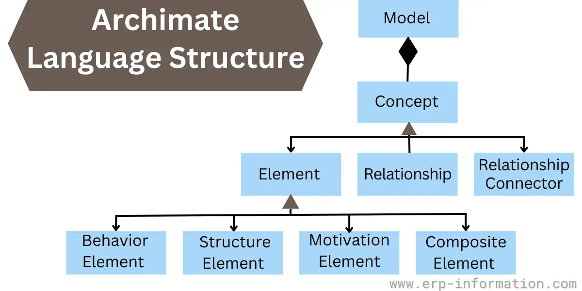
ArchiMate Elements
ArchiMate elements are broadly classified into
- Behavior and Structure Elements
- Specializations of Structure and Behavior Elements
- Motivation Elements
- Composite Elements
Behavior and Structure Elements
Three elements under this. They are Active Structures, Passive Structures, and Behavior.
Active Structures
These are the elements that represent things that can perform actions. ArchiMate’s active structures include application components, business actors, and business roles.
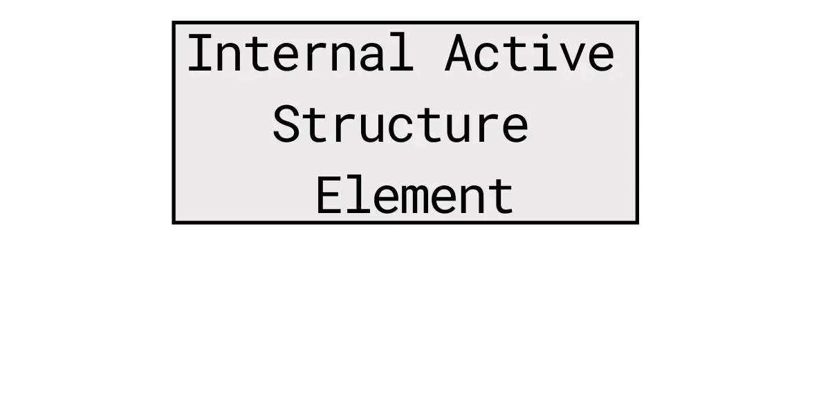
Internal active structures are represented using boxes with square corners or an icon in the upper right corner. It indicates an entity that is capable of performing the behavior.
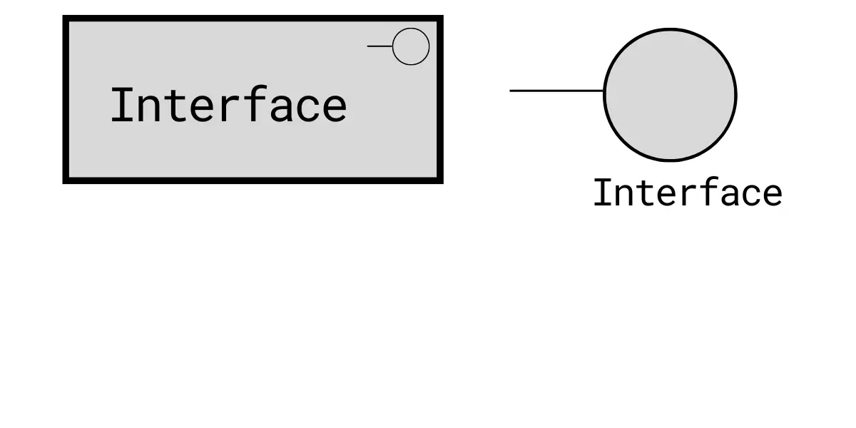
External active structures are represented using a point of access where one or more services are provided to the environment.
Passive Structures
These elements represent physical or abstract objects within the system on which behavior is performed. For example, ArchiMate passive structures include databases, files, resources, and artifacts.
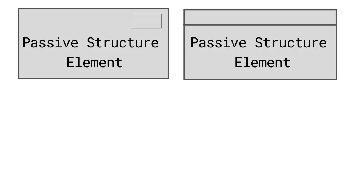
A passive structure element represents an element on which behavior is performed.
Behavior
These are the elements that represent the actions performed by active structures. It includes processes, services, and events.
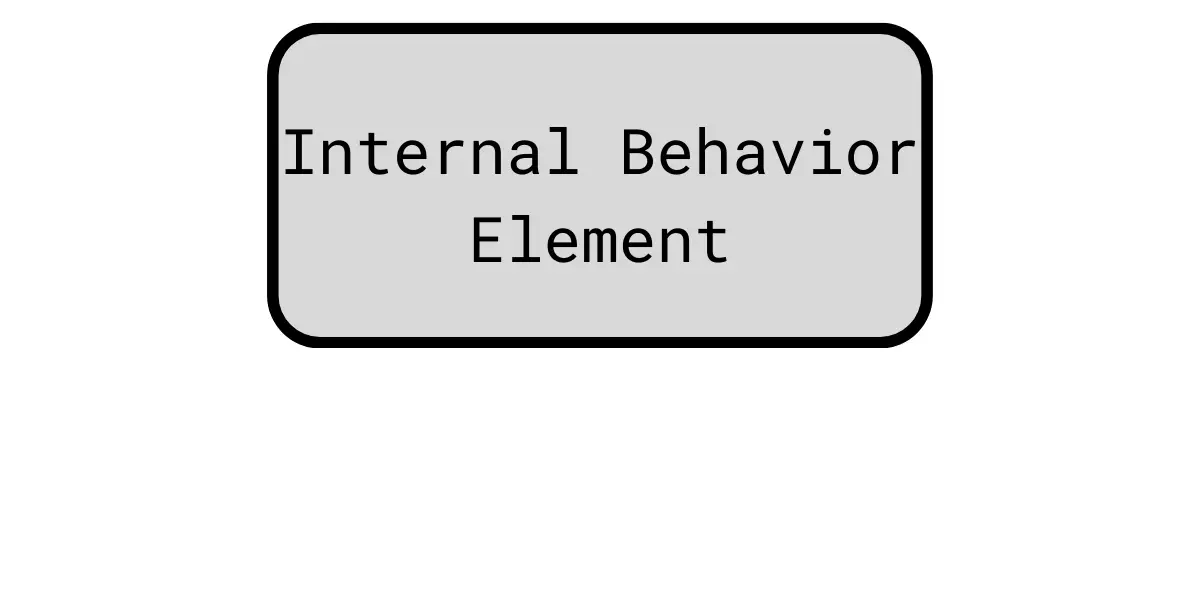
The internal behavior element denotes an activity that can be performed by an active structure (active structures may be one or more).
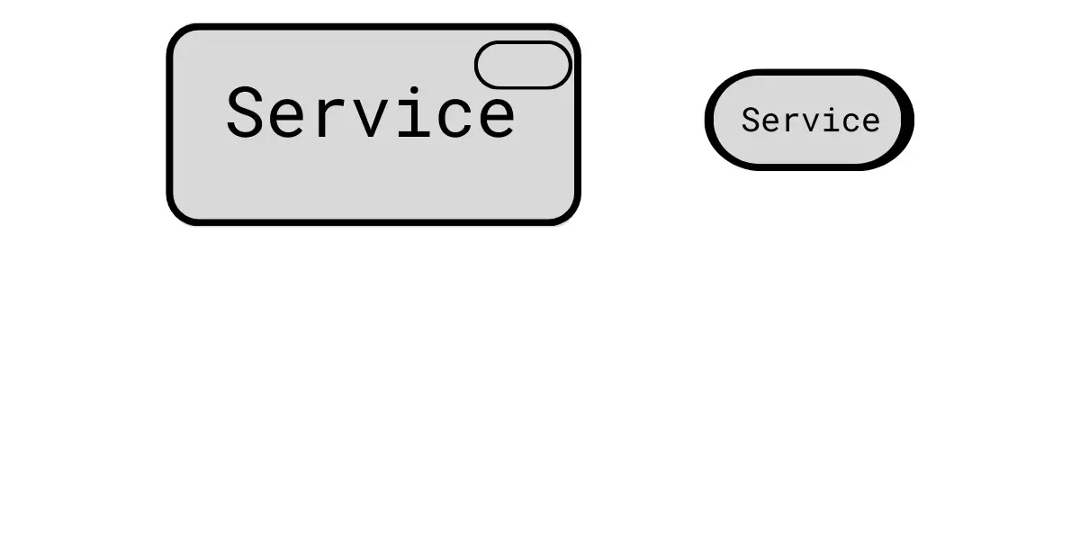
The external behavior element also called a service, denotes defined exposed behavior.
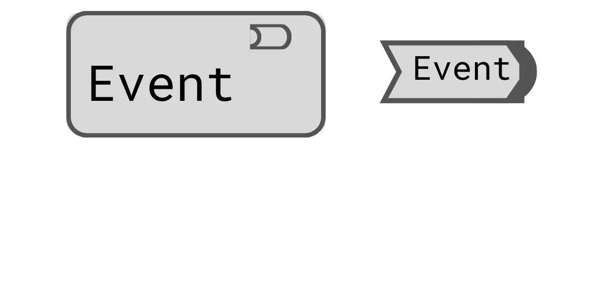
An event denotes a state of change.
Specializations of Structure and Behavior Elements
These are the elements that show relationships between functions, processes, and interactions. That includes process, function, interaction, and collaboration.
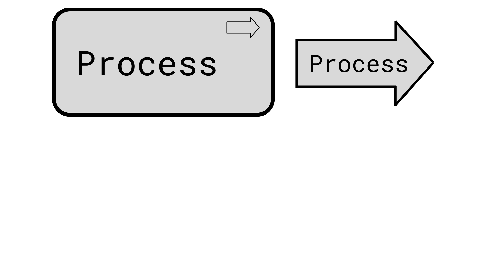
A process denotes a sequence of behaviors that achieves a specific result.
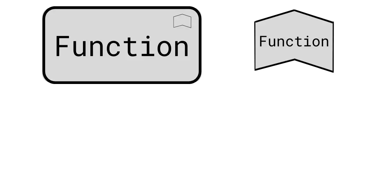
A function shows behavior collection depending on particular criteria like location and resources and is implemented, managed, and performed as a whole.
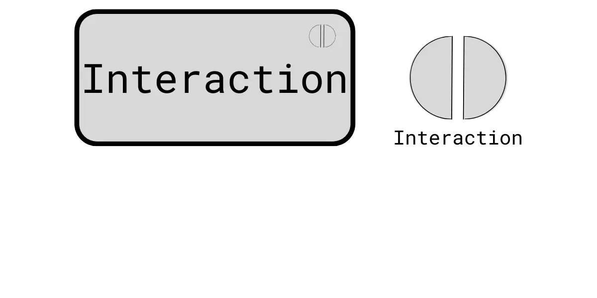
An interaction shows a collective behavior unit that is performed by more than one internal active structure element.
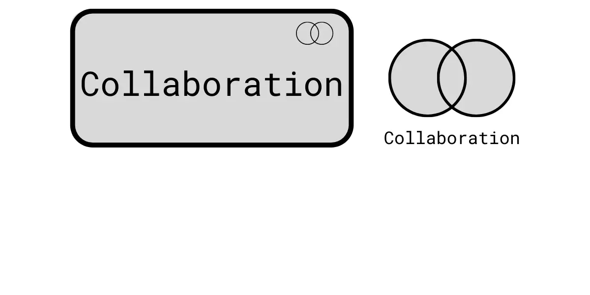
Collaboration denotes the aggregation of two or more internal active structure elements. They work together to perform collective behavior.
Motivation Elements
These are the elements that denote stakeholder, value, driver, meaning, outcome, goal, assessment, principle, requirement, and value. The below notation shows the generic motivational element.
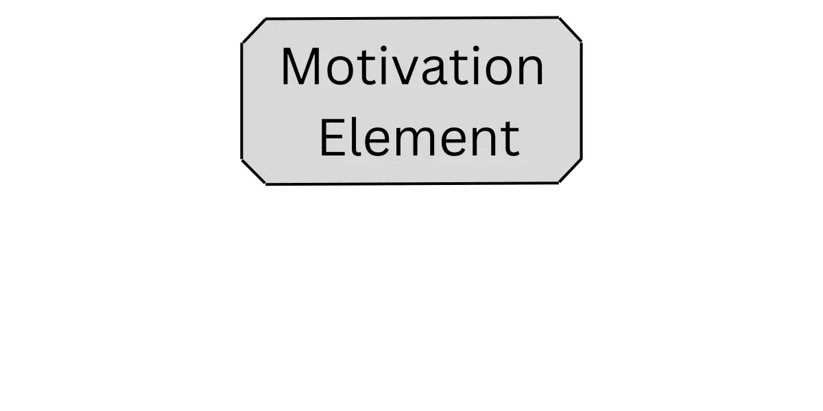
The motivation element shows the context or reason behind the organization’s enterprise architecture.
Composite Elements
These are the elements that represent other concepts from multiple layers of the language. Grouping and Location are general composite elements.
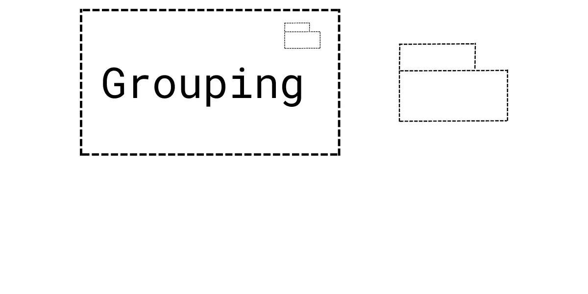
Grouping represents the aggregation of concepts that belong together based on some common characteristic.
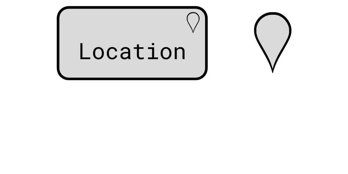
Location element denotes a conceptual or physical place where concepts are located or performed.
ArchiMate Relationships Examples
Structural Relationships
- Composition relationship – It indicates an element consists of one or more other concepts.
- Aggregation relationship – It indicates an element combines one or more other concepts.
- Assignment relationship – It indicates the allocation of responsibility, the performance of the behavior, storage, or execution.
- Realization relationship – It indicates an entity plays a critical role in the creation, achievement, sustenance,
Dependency Relationships
- Serving relationship – It indicates an element provides its functionality to another element.
- Access relationship – It indicates the ability of behavior and active structure elements to observe or act upon passive structure elements.
- Influence relationship – It indicates an element affects the implementation or achievement of some motivation element.
- Association relationship – It indicates an unspecified relationship
Dynamic Relationships
- Triggering relationship – It indicates a temporal or causal relationship between elements.
- Flow relationship – It indicates a transfer from one element to another.
Other Relationships
- Specialized relationship – IT indicates an element is a particular kind of another element.
Relationship Connectors
A junction serves as a connector in various scenarios to link relationships of the same type.
When it comes to creating a path with junctions connecting such relationships between two concepts, there’s a crucial rule: a direct relationship of that type must already be allowed between those concepts.
In simpler terms, junctions can’t be used to establish relationships between concepts that wouldn’t be permissible otherwise.
A junction can have multiple incoming relationships and one outgoing relationship, one incoming relationship and multiple outgoing relationships, or multiple incoming and outgoing relationships (which is essentially a condensed representation of two consecutive junctions).
The relationships compatible with a junction encompass all dynamic and dependency relationships, along with assignment and realization.
A junction is employed to explicitly indicate that either all the elements involved must be part of the relationship (and junction) or that at least one element must participate in the relationship (or junction).
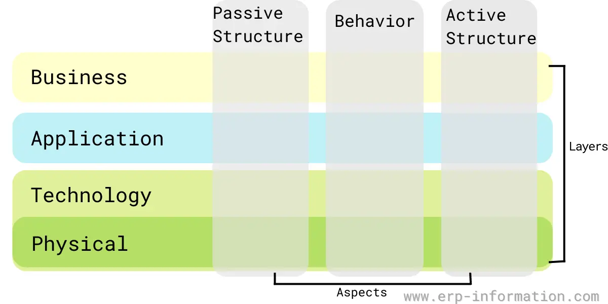
The ArchiMate Core Framework
The core framework consists of nine cells that classify the archimate core language elements. It is made up of three aspects and three layers.
Elements are categorized based on aspects and layers. However, when constructing real-life architectures, it’s important to note that the different aspects and layers should be interconnected through elements that connect them together. That is essential for creating a comprehensive architectural description.
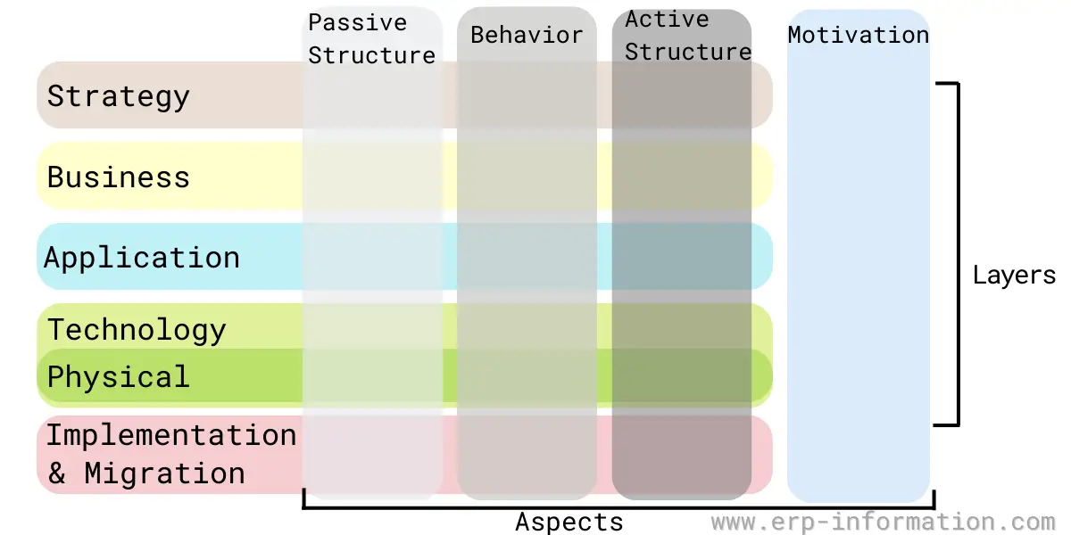
Full Framework
It is the same as the core framework, but an extra layer called strategy and an additional aspect will be added. The technology layer includes physical elements for modeling equipment, distribution networks, and physical facilities.
Colors and Notational Cues
As you can see in the above image, the colors and notations of the Archimate model are as follows.
- White color for abstract concepts
- Light grey color for passive structures
- Medium grey color for behavior
- Dark grey color for active structures
There are no standard rules or restrictions for colors. It is left to the modeler. However, many of them follow these colors to differentiate the archimate language layers.
- Yellow color for the Business layer
- Blue color for the Application layer
- Gree color for the Technology layer
Notations for different layers are as follows.
- Letter M in the top-left corner of the element represents the Motivation layer
- Letter S in the top-left corner of the element represents the Strategy layer
- Letter A in the top-left corner of the element represents the Business layer
- Letter T in the top-left corner of the element represents the Technology layer
- Letter P in the top-left corner of the element represents the Physical layer
Some standard notations for different element types are
- Square corner for structure elements
- Round corner for behavior elements
- Diagonal corner for motivation elements
The Benefits of Using ArchiMate
There are many benefits to using ArchiMate, including the following:
- It is a well-established and widely used modeling language.
- It is vendor-neutral and can be used with any enterprise architecture toolset.
- It is comprehensive, covering all aspects of enterprise architecture.
- Finally, it is flexible and can be customized to fit the needs of any organization.
Latest ArchiMate Specification
Architecture modeling has gained a lot of popularity in recent years. Many architecture modeling languages exist, but the ArchiMate language is one of the most popular. It is used to create diagrams that show the structure of architecture.
The latest version of ArchiMate is 3.2 specification. It was released in October 2022. It includes many new features. Some new features include a value stream element, a directed notation for the association, and refinement of the rules for deriving relationships.
The ArchiMate 3 specification is a comprehensive guide to creating ArchiMate diagrams. It covers all aspects of the language, from basic concepts to more advanced topics. It is an excellent resource for anyone who wants to use ArchiMate.
ArchiMate Modeling Tools
1. Visual Paradigm
It is a certified ArchiMate modeling tool.
Features
- Drag and drop editing interface
- Alignment guide
- Formatting options for shapes and connectors
- Custom viewpoint
- Reuse of the same elements in different diagrams
- Online view of diagrams option for stakeholders and teammates
- Cloud platform
Pricing
It offers four plans.
- Modeler – Charges $99
- Standard – Charges $349
- Professional – Charges $799
- Enterprise – Charges $1999
2. Archi
It is an open-source ArchiMate modeling toolkit that helps to create ArchiMate models and sketches.
Features
- Supports the latest version, which is ArchiMate 3.1
- Generates ArchiMate views and viewpoints
- It gives hints about using elements and relationships
- Visualizer helps to connect the dots
- It offers cross-platform and is written in Java
- Sketch view for sketching your ideas
- Canvas modeling toolkit to create your canvas
Tips for Creating an ArchiMate Diagram
- Start by creating a basic sketch of your diagram on paper. That will help you plan the overall structure and ensure all your ideas are included.
- Use clear and concise titles for each of your ArchiMate elements. It will make it easier for others to understand your diagram.
- Make use of layers to control the visibility and hierarchy of your elements. It will help you create a more organized diagram.
- Use connectors to link your elements together. That will create a more fluid and cohesive diagram.
- Use colors and shading to differentiate between different elements and groups of elements.
- Be consistent with your use of notation throughout the entire diagram.
- Proofread your diagram for errors and ensure that it is properly formatted.
Conclusion
ArchiMate is a comprehensive modeling tool used to create diagrams of enterprise architecture. This post has provided an overview of the ArchiMate elements and layers and tips on creating effective ArchiMate diagrams.
Knowing the concept and tools outlined here allows you to create clear and concise diagrams that accurately represent your system architecture.
References